February 2014
Setting up your station can be a bit of a pain. The good news is that with newer radios it gets very easy compared to the goo ole days.
In the past you had a separate box for each function. Go back to the 1960s and you had a receiver, transmitter, maybe an R/T antenna switch that also muted the receiver, trans-match (antenna tuner), SWR bridge, and on and on.
More modern HF radios are now Transceivers (Receiver, Transmitter, switching circuits all included). In the 1970s you still had narrow band tube finals, so you had to learn to tune the transmitter to your antenna. You dipped the plate current and increased the load (the circuit in the radio was a pi network and you had two variable capacitors and an inductor in the output tuning circuit (just like your antenna tuner), the coil was taped for each band covered but the plate and load capacitors needed to be adjusted for each frequency within the band. Most of these radios would load between 50 ohms to 75 ohm antennas. Now most radios are looking for a matched 50 ohm load with NO final tuning. But we still find that we need to watch the SWR on these new radios. On the bands above 20 meters most antennas, once set to the either the SSB sub-band or CW sub-band need no other tuning. It is on the 160, 75/80, 40 and 30 meter bands where most antennas will only have a 2:1 or less on a portion of the band. My recent experience bears this out. I was rag-chewing on 7.245 MHz using a solid state radio at 100 watts. My logging software received a DX spot at 7.165 Mhz. Just 80 KHz away. I hit the F11 Key which tuned the radio to the frequency and mode, identified the station and when it was my turn, made the call. No luck, I turned on the amplifier that was already set up on 40 meters and made the call with 500 watts out (I was using the dipole). Got the DX!, but I noticed that my SWR was up around 5:1. That’s not so good. Lucky for me that the amplifier and radio are well protected.
Lesson is: Even with modern NO TUNE radios, we still need to make sure that we have a good match to the antenna system.
73 Rick N4ASX
Larry’s Homebrew
The purpose of this paper is to review the PSKMeter kit being sold by KF6VSG.
Those of us who have used PSK31 and PSK63 in the past have seen strong signals on the waterfall display blank out all others. This happens when a person through ignorance or malice cranks the power up to 50 or 70 watts or higher in PSK mode. That produces distortion and unwanted harmonics and annoyed fellow Hams. It is essential that we operate our transmitters in as linear a mode as possible to communicate well, minimize distortion and live happily with other amateurs.
The most effective linear operation occurs when the Intermodulation Distortion (IMD) is in the rangeof -25 db to -30db. Much higher than -30 db and you are trading signal power for fractional improvement in IMD reading. Much lower than -25 db and you are distorting. So, how do you know what’s enough power and what’s too much? Well, you can have another ham observe your signal on his display and to relay you the IMD setting, but it would be great to have a monitor that could be sitting in your shack giving you constant readings.
Such a monitor is available as a kit by KF6VSG atwww.ssiserver.com/info/pskmeter
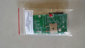
Figure 1 – PSKMeter circuit board kit
Shown above is the kit as it arrives in a Ziploc package. The circuit board is well-designed and soldering is quite simple and straightforward. The package includes all parts for the circuit board and assembly instructions. The kit includes a pre-programmed micro-processor, a 20 MHz crystal, a voltage regulator chip and assorted resistors, capacitors and connectors. The parts are well-marked and someone has said the instructions resemble early Heathkit ones. Assembly took about an hour max. Assembly is in two stages: everything prior to a power on smoke check (micro processor not yet installed) then remaining parts are installed and a further checkout is done with the PSKMeter attached to a PC.
Figure 2 is a shot of the board after assembly. The PSKMeter inserts between the transmitter and antenna using a T-connector. Unfortunately it is a BNC connector so adapters are necessary to connect with most Ham equipment. Tuneup and calibration of the circuit is best done with a dummy load. There are two software packages available. Both are free. The best one in my estimation is called Psk Scope http://www.softpedia.com/get/Science-CAD/Psk-Scope.shtml. It has a software slider to change power settings and readings that include a visual signal display, the number of the comm port being used, IMD, RMS signal voltage, Peak signal voltage and output power in watts. By connecting your PSKMETER (board) to a free comport on your computer (or connecting to a USB port with the optional Serial/USB converter), connecting your transmitter’s RF output via a ‘T’ connector, and running the PSK Scope software application, your signals can be perfectly adjusted.
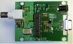
Figure 2 – Assembly complete
An enclosure is available for around $2. Once the circuit board is installed in the enclosure it should resemble Figure 3, below.
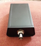
Figure 3 – Unit assembled inside cover
Note: The documentation refers to idling power. This is when you key the transmitter but are not actually sending data. You set the power level and IMD using idle power. (When actually transmitting data the IMD setting may or may not be accurate).
The assembled unit performs as advertised and has been functioning in my shack for about 2 weeks. No problems have been noted.
The next page (Figure 4) shows the PSK Meter in operation using the PSK Scope software. The signal pattern is green indicating a good signal. Other data being shown include that we are using Comm Port 7, the IMD is 30.3 db, RMS is 0.65 v, Peak voltage is 3.37 and Power Out is 29.0 watts.
Price Data:
PSKMeter $41.40 plus shipping. Data cable, power supply and enclosure available at extra cost.
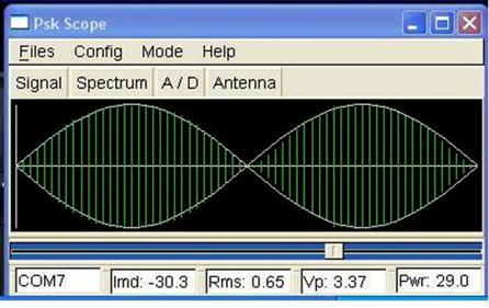
Figure 4 – PSK Scope in operation
September 2013 ELMER’S Corner – Mobile Antennas
Many new hams start with a handheld because it’s an all in one arrangement. All self contained, no need for a power supply, additional antenna / feedline or external microphone. But, soon after we all find out that the antenna on the radio is not good for any real range. The next step is usually a mobile whip of some kind put on a metal plate or file cabinet. This magnetic mount antenna also works for going mobile.
We’ve covered some homemade portable antennas, but let’s look at mobile whips. In the past we worried about ONE band at a time, but many now have dual band radios (2m/70cm) and there are many mobile antennas that will do this.. One we overlook is the 2 meter quarter wave. A 19.25” whip. Because 70cm is the third harmonic of 2 meters, the simple quarter wave will work on 70cm. Nice thing about the quarter wave is that it is small enough so that it can be placed on the roof of your car and not cause in door parking problems.
If your working just one band or need more gain, look at the 5/8th wave antennas. This antenna flattens the pattern and give you an effective 3db gain so your 5 watt handheld sends out 10 watts Effective Radiated Power (ERP). Unfortunately, the 2 meter 5/8th wave will not work on 70cm, but it will work as a ¼ wave on 6 meters. Some of these antennas can be found at hamfests cheaply.
There used to be many types of mounts that could be found either on mag mounts or as installable by drilling a hole in the vehicle. These days the most popular is the NMO or Motorola mount. Shop around for mag mounts they can be expensive. I purchased one with a BNC connector for $32. The advantage is that you can use it in the home or on the vehicle.
I have also used the 3/8s thread mounts which are common to the HF whips and CB whips. At hamfests you can find the Hustler 5/8ths antennas (Buckbuster) fairly cheaply and Hustler use to make a family of collinear antennas that provided 7db of gain but it is a BIG antenna and it only works on 2 meters. I have one for 2 meters and one for 220MHz and they work well.
Comet and Diamond make dual band and other antennas that work well but any multi-band antenna will be a compromise.
73 Rick N4ASX
August 2013 ELMER’S Corner – HF Antennas cheap and stealthy
With VHF and UHF we found that you can make several inexpensive antennas. VHF and UHF antennas are small by comparison with HF (High Frequency) antennas. The fundamental focus should that the size of the antenna is related to the ¼ wavelength of the frequency. So
| Band | Frequency(MHz) | 1/4 wavelength |
|
|
|
|
|
|
|
|
|
|
|
|
|
|
|
|
|
|
|
|
|
|
|
|
|
|
|
|
|
|
|
|
|
|
|
|
As you go down in frequency your antenna must be larger. While there are LOTS of small antennas that suggest that they can perform as well as larger antennas, the math does not support the claims.
The simplest antenna is a dipole (2 ¼ wavelength wires attached to the coax center and ground. But many of us cannot run a coax out to the center of a dipole and stay stealthy. Two alternatives for a resonant antenna are a vertical which can be a vertical dipole or a ¼ whip with a ground plane. For the 20 meters you might run a vertical wire from the ground up into a tree and run four or more quarter wave radials (wires along the ground or buried in the ground. If you can mount the vertical radiator on a metal plate you are in good shape. When the sunspots are high then you might go with a 10 meter vertical and you could use an old CB (11 Meter) whip and cut it down.
One of our members has a copper water pipe antenna. He uses heavy pipe with a threaded coupling so he can make it 10 meters, 15 meters or 20 meters. He uses hook up wire for the radials and a screwdriver stuck in the ground to insulate the radiator from ground.
One other member used aluminum drain pipe on a wine bottle as the vertical.
Another alternative is the random wire. If you can put lots of wire between your balconies or someplace close to the feed point you can run the coax outer conductor to ground and attach your wire to the center conductor and run as MUCH wire as high as you can. You can use copper weld or other light weight wire so that it’s hard to see and run it to a faraway tree. As this is a non-resonant antenna, you will need to use an antenna tuner to make the wire antenna resonant for each band you operate. One ham was on the 9th floor of an apartment and ran 250 feet of thin magnet wire to a fence around the parking lot and he worked over 200 countries on 100 watts.
Mobile whips will work but they are inefficient and usually on resonant for a narrow range of frequencies, but if you put a ¼ wavelength wire counterpoise or two or more radials you can still work the world.
July 2013 – A Cheap 220 Mhz Yagi
Good news! The Alexandria Radio Club has an operative 220 Mhz repeater. The only problem for me was how to hit the repeater with a handheld radio from where I live (in Burke,Va).. Five watts is not a lot of power so an antenna was needed that would provide some gain. Three to 5 db gain would be great. Oh, did I say also cheaply?
DESIGN
A good discussion for the beginner to Yagis is athttp://www.hamuniverse.com/yagibasics.html
I needed a suitable design for the frequency of interest 224.82. A quick way to obtain a designed antenna was to use the QY4.exe tool developed by WA7RAI.. It may be found at http://www.dxzone.com/dx451/quickyagi.html Under the Quickyagi icon you will find a link: http://www.astro.hr/ucionica/radioastronomy/antenna/qy4.zip
Download the file and unzip it. QY4 is a DOS program and is old, but useful and free. A setup file to install the software is included with the downloaded zip file. I used the Auto Mode selection for design and selected “Auto-design a Yagi”. You will next be asked for the following:
- Frequency? 224.82.
- Are all elements the same diameter? Y
- # of Directors? 2 (I only selected two directors to keep the size small).
- Element Diameter? (I answered .1 inches – the diameter of the welding rod to be used.
Next QY4.exe will give you the design data for the antenna
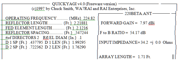
You could actually stop here and have a useable antenna. However note the input impedance of 34.2 Ohms. You can opt to use a 2:1 Balun to match closer to the 34 ohms (more expense) or if you just use the 50 ohm cable losses are not too high. I just used an unbalanced connection and matched directly to the 50 ohm coax. After all ,we are going cheap, here.
For my antenna, I elected to use another piece of software EZNEC ver. 5.0.54 by Roy Lewallen. It is $89 or if you choose to just use the Demo version, free. www.eznec.com/demoinfo.htm (The Demo version is restricted in the number of segments allowed to 20 whereas the commercial version allows use of 500 segments). Even with only 20 segments you can still design simple antennas.
I input the information from the Quick Yagi output into EZNEC5’s input side and optimized the gain for the planned height above ground by adjusting the driven element dimensions in EZNEC. Finally the results were as good as could be done quickly and I was ready to build the antenna.
Construction
To start the project, a quick survey of the junk box. Things I found were short pieces of wood from past projects, some scrap sheet metal and a piece of coax with a connector attached. Now suddenly I saw a package of acetylene welding rod not currently being used that was copper coated .
(See list of materials used, below)
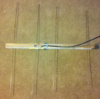
First step was to select a piece of wood large enough to accept the welding rods and antenna connections. As you will notice on the Quick Yagi output the boom had to be over 1.71 ft in length to hold all the Yagi elements. A piece 24 inches long by 1 inch wide was available in the scrap box, so it was used.
Next the holes were drilled for the welding rod elements. (Be sure to make the holes a snug fit for the elements otherwise they will slide around when finished).
I inserted the welding rod for the driven elements into some solderless fasteners to provide a connection that could be removed if needed. Then the elements are inserted into the wood and centered. Notice the driven element consists of two individual pieces and that they do not touch each other.
The Coax connector cable ends were soldered to each of the driven element connectors using the solderless fasteners.
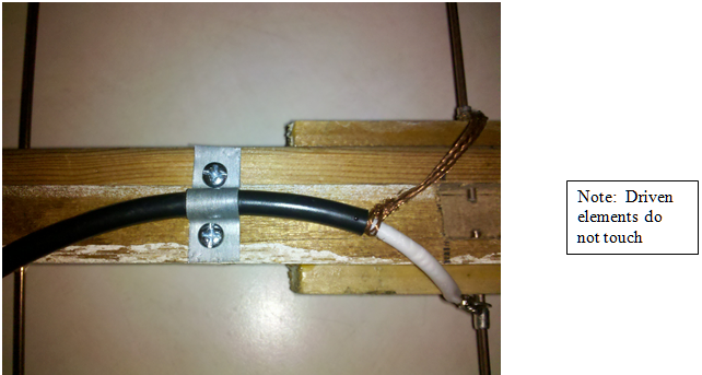
The frequency of 224.82 Mhz is above what most antenna analyzers can handle. So tuning is really dependent on an accurate design.A clamp for the coax was made from a scrap piece of sheet metal and secured with two screws.
Note that if this antenna is used outdoors the wood parts of the antenna should be painted with polyurethane or some weather protectant. Also the metal elements could be sprayed with clear lacquer to protect the copper. If used inside be careful of large metal objects – particularly metal window frames. They can really adversely affect the VSWR and the gain.
If you have questions, you may email me at KK4CBL@arrl.net and I will attempt to answer your questions. 73s, Larry Walker KK4CBL
July 2013 – Antenna Feedlines and Connectors
So far, we covered buying used radios, cheap antennas and power supplies. Let’s talk about antenna feedlines and connectors. I was getting ready for Field Day and putting the newsletter and I read Harry’s meeting minutes. The simplest VHF antenna is the roll up J-pole with the details in the May ARC SHORTS. It dawned on me that most of those who will want to build one of these antennas will want to use it with their handheld VHF radios. In the past these radios had BNC connectors so we used BNC to PL-259 (UHF) adapters, but now handhelds use an SMA connector. SMALL and maybe a bit difficult to put on our antennas. BUT, I wanted to give it a shot, so I called my favorite connector, cable place and ordered a bunch of connectors including some RG-8X SMA male connectors. WOW – in one paragraph I tossed a great deal of jargon at you and your lost in it. DON’T STOP READING – I Shall endeavor to explain.
There are two types of feed lines for antennas, the balanced line or twin lead that we use to use for our TV antennas. Twin lead is very efficient but can be a pain to feed through a wall or work with. Good for HF but not so good for 50 MHz and up. COAX is the cable with a center conductor, an insulator around that center conductor and an outer conductor over the insulator and then an outer plastic or rubber jacket. It comes in several impedances (50, 75, 92 ohms) we are interested in the 50 ohm cable. Now there are THREE sizes that we generally use. The big stuff is 5/8 in diameter can be RG-8, RG-213 (Mil Spec RG-8), Low loss versions are LMR-400 or 9913. There are charts in the ARRL handbook and antenna book to show the loss of each type of coax. This stuff is great for the home, but can be a problem when portable or installation in a car. The next step down is RG-8X. This is the smaller diameter stuff and 8X is almost as good as RG-8. I use RG-8X for mobiles, and portable / Field Day / Public Service operations. 100’ of this stuff is a lot easier to deal with then 100’ of RG-8. If you’re going CHEAP, then there is RG-58. This is slightly thinner than RG-8X and not near a good, but it’s the stuff you can buy at Radio Shack for 19 cents a foot or less.
Most mobile radios (CB’s as well) have a standard Coax connector on the back. In the industry it’s called a UHF connector. The female connector is also known as an SO-239 and mates to the PL-259 on the coax feedline. So, if you buy a VHF mobile you will want to make up a feedline with a PL-259 connector that goes with the coax you chose to use. If your using a new handheld the little connector on the handheld is an SMA connector. Most of us do not put the SMA male connector on the coax, but buy an adapter to convert the SMA to the UHF Female (SO-239) and then connect our coax with the PL-259s to the adapter. Some adapters convert to a BNC connector. The BNC is what was used on UHF and up radios and handhelds before the SMA. It’s a bayonet type connector. An important point here is that adapters cost power on transmit and some receive sensitivity.
Now we have three kinds of coax and three different kinds of common connectors. Now I will toss in one more variable. Two kinds of connectors. The standard for most is the solder on connector. The solder on UHF (PL-259) for RG-8 you cut the outer conductor back exposing a length of the center conductor and insulator and cut the insulator back so you have a little exposed center conductor (about ½ inch) another 1/16 inch of insulator and then about ½ inch of outer conductor exposed. You first put the screw collar over the coax, then you put the connector body over the end of the coax and screw the outer conductor into the connector body while having the inner conductor feed into the center pin of the connector, solder the inner conductor to the pin and there will be holes in the outer side of the connector body that will show you the outer conductor. This becomes a talent issue. You want to place solder into those holes and get a good solder connection WITHOUT melting the insulator between the inner and outer conductor of the coax or the insulator in the connector. I use a 250 watt soldering gun for this.
Another approach is the CRIMP on connector. About the same initial fit up but you also put a collar over the cable with the screw on piece. Solder or crimp the center connector and then the insulator goes inside the connector body and the outer conductor goes outside the connector body, then there is a crushable collar that slides over the outer conductor. Here is the fun part, you get your crimping tool and crush or crimp the collar down onto the outer conductor. Faster and unless your really good with the soldering gun works better. The cost of the Crimp kit is about $100 but the connectors are about 50 cents cheaper and not redoing the connectors will pay off.
Now if your using RG-8X or RG-58, the solder on connector is the same but you add a sleeve over the smaller coax. There solder on PL-259 can be more like the crimp connector. The outer conductor is folder over the adapter sleeve. And then the coax with the adapter is put into the PL-259. Solder the center pin to the inner connector and then with two pairs of plyers you tighten the adapter into the body. You can then solder through the holes in the connector body, but you don’t need to if you can tighten the adapter. Crimp on connectors for RG-8X and RG-58 work like the standard but have a smaller body for the smaller coax, no adapters to buy or look for.
If your working with older radios or military gear you may have to work with the BNC connector. One of our members called these BAD NEWS CONNECTORS. The center pin is soldered to the inner conductor and any excess solder may cause problems
June 2013 – Power Supplies
Last month I talked about cheap, homemade VHF/UHF antennas. I’ve already gone over the availability of used and inexpensive VHF equipment.
Now you find that your new handheld doesn’t quite make it to the repeaters you want to operate on so you’ve tried an antenna from the list of DIY designs and still not good enough. You’ve also found out that needing to recharge your handheld batteries is a pain and holding you radio sometimes leads to hot radios and lots of weight.
The next step is to find a used mobile two meter radio and as we covered before, you get one with CTCSS / PL encode and between 10 and 50 watts output. Now comes the need for a power supply to make it work. Your happy that you only paid $100 for the radio and $15 in parts and coax for your antenna, but now you find you need a power supply for that new radio.
Now, How many amps do you need. If your running your handheld at 5 watts then figure P = IE with 5 watts out this would indicate that you need 5/12 amps, but you also need to remember that the output is only from the final amplifier of the radio and does not cover the other components. Best rule of thumb is to go for 5/12 * 2 (assume that you will need twice what the finals use). So for your 5 watt handheld you need about 1.7 Amps. There are many 7 Amp and 10 Amp supplies available that will work. If you’re running a 10 watt radio that would be about 3.5 Amps on transmit but again 7 or 10 are available. For a 50 watt radio most of us would go with a 20 Amp supply. The 20 Amp supply will provide sufficient current for a 50 watt or more mobile and also sufficient current for most 100 watt class HF radios as long as you do not transmit on both at the same time.
If you go for a commercial power supply, there are two kinds. One is the basic power supply and the other is a switch mode power supply. The switch mode power supply converts the incoming AC into DC then converts it to AC at a high frequency. The higher the frequency the small the transformer. Switching supplies are more expensive but much smaller and lighter.
Several solutions come to mind.
1 – You can build your own. You will need a AC cord with plug, a transformer from 117AC to 24 -30 Volts AC, Diodes that can handle the current you need, a few electrolytic capacitors and maybe an inductor to filter the rectified AC. See the Amateur Radio Handbook or the web for detailed designs. Not a hard project, but,
2 – Look for a used power supply at a hamfest or from someone in the club. New commercial power supplies go from $60 to $200 for the kind of current you might need, so you should not pay more the $70 the basic 12 VDC supply.
3 – A cheap way to go is also to find a car battery ( or marine deep cycle battery) or even a 35 Amp Hour sealed cart battery can work and buy a cheap car battery charger. The battery provides the filtering and high current when needed and on receive. If you have a car battery you’ve recently replaced then all you pay for is the core charge. You will find that buying a new battery may set you back as much as a new power supply, but you will also get a back up source when the power goes out.
4 – Buying a new supply. Good names are Astron, MFJ, Radio Shack, Samlex, Jet Stream and Diawa. Most of them have good protection circuits and many now have Anderson power poles. These power supplies (20Amps go from as low as $85 (MFJ).
If I had an old car battery, I would start with that, and then go to the hamfest looking for a used power supply. Take a volt meter with you and have your ELMER look at it if you have any questions. The Astron 20 Amp power supplies sell on the web for $120 new. Some of the switching supplies can be had for the same price on Amazon or fro
m ham radio stores, so offer less for a used unit. A new power supply is not a bad investment as it will also support other gear.
Connectors are a consideration. Most VHF/UHF radios now use a T-Connector but many of us use Anderson power poles. Rather than cut the T-connector, I usually leave the T-connector in place and put Anderson 20 Amp power poles on the cable. If the power supply has binding posts, make up a short piece of 10 gauge red/black cable with Andersons on one end and ring connectors for the binding posts on the other. Just wrapping stranded wire on the binding posts will cause problems later.
May ’13– VHF Antennas for Tech and others
Our weekly nets do not reflect the club’s membership. Some of the problem is that the success of our classes has brought in many new members. Ham radio can be a very expensive hobby with the old Cushcraft Ringo costing over $100 and the Diamond and Comet sticks costing even more, may keep some of our new operators from putting up an antenna for 2 meters. Another issue may be restrictions place on us by home owners associations or building management.
There are some stealthy solutions. The first is the ¼ wave ground plane antenna. All you need is 5 – 19” pieces of copper wire (from 10 Ga. Romex is ideal). Take an SO-239 chassis connector and solder the vertical element into the center of the connector, try not to melt the insulator. Then you can solder the four ground plane elements to the four screw holes, but if you want to add a mount you can bend a small piece of sheet metal and drill a hole for the connector and the four mounting holes and use four screws to secure the connector and the radials to the mounting plate. Drill holes for a U bolt to secure the antenna to a small piece of 1.25 in TV mast. Feed it with a small run of RG-8X or RG-58 with a connector that matches your radio and you will have a much better antenna then the rubber duck on the hand held. Another cheap antenna is the coaxial dipole. Take one end and fold back the 19” of the outer conductor back over the plastic outer jacket of the coax leaving 19” of the inner conductor and insulating jacket exposed. At the end of the outer conductor make an RF choke by rolling up four 6” diameter loops and taping them together. The remainder of the coax should reach your operating position. Add your connector for the radio at the other end. You can hang this antenna up either outside or near a window. Another design that has some gain is the J-pole which can be made with TV Twin lead or ladder line.
Tools: Ruler, Wire strippers, Wire Cutters, SolderingIron.
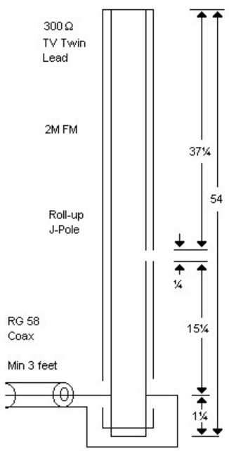
2 Meter J Pole Antanna
- Measure 54″ of Twin lead and mark this spot with some maskingtape. Cut the wire about 1 ½ inches longer than this measurement.If this is your first attempt at building something, you may want to leave4 ” of extra wire on the piece you are working with. This will allow anadditional attempt of the critical portion of construction.
- Remove the center insulation from the bottom 1-inch of twinlead. Strip the insulation off of the bottom section of twin lead (onlythe 1 “). Connect the wire together at this point and solder.
- From the splice you just made at the bottom, measure up about1 ” and remove ½ ” – ¾ ” of insulation from each conductor.This is where we will be attaching the coax.
- From the splice measure up one side 16 ½” . CHECK THE MEASUREMENT TWICE. Cut a gap on this side about ¼” wide. Besure to remove the conductive material from the notch.
- From the splice, re-measure the total length to 54 ” andtrim the top.
- Attach some coax to the opened area of the wire about 1 ¼”from the splice. The shield of the coax MUST connect to the notched side.
- Attach a suitable connector on the end of the coax for your transmitter and GO!
March ’13 – HF antennas for small spaces.
Most of us now get started on VHF with the Tech license, but very shortly afterward we feel the need to talk beyond the line of sight. HF is a GREAT part of the hobby. Radios, even 20 year old radios, have great specs, are solid state, usually have digital read outs and run on 12 Volts. You no longer need to have a table full of gear to have a very capable HF station. But the radio, and power supply are not a big issue. Your enjoyment of HF will be related to how well you hear and how well you are heard and that my friends comes down to ANTENNAS.
Keep in mind that smaller antennas are easy to hide, easy to put up and don’t hear or transmit as well as longer wire antennas. Many of our members use hamsticks or other mobile whips set up on a mount on a balcony or in a window. They do work but are not very efficient. Adding a counterpoise (1/4 wavelength wire on the ground for the band of interest) will greatly help the performance of these mobile whips. Small whips give up bandwidth. You will need some form of antenna tuner for 75 and 40 meters and maybe for 20 meters.